index-bg-11

2026 How to Choose Underbody Telescopic Cylinders?

Choosing the right Telescopic Cylinders Underbody system in 2026 requires more than comparing stroke length and price. The cylinder sits beneath a working vehicle, exposed to road spray, gravel, vibration, uneven loading, and rushed maintenance. Every detail matters.

Hydraulic equipment specialist Daniel Mercer says, “A reliable telescopic cylinder begins with the application, not the catalogue.” That principle deserves attention. A cylinder designed for short urban deliveries may fail early on quarry roads. Likewise, a powerful unit can be wasteful when the payload is modest. The wrong choice may still look correct during installation.

This guide examines bore size, closed length, lifting angle, operating pressure, mounting clearance, and material protection. It also considers oil quality, seal design, lubrication access, and frame alignment. These practical factors shape service life more than impressive specifications alone.

Measure twice.

Underbody clearance is often underestimated. A few millimetres can decide whether the cylinder avoids a crossmember, axle movement, or accumulated mud. Buyers should inspect the complete tipping cycle, not only the parked position. They should also verify compatibility between the pump, valve, hydraulic oil, and cylinder rating.

There is no universal best cylinder. That is the uncomfortable part. A cheaper model may perform well in light-duty service, while a premium cylinder may be necessary for frequent high-pressure cycles. Manufacturer documentation, field experience, and competent installation should guide the final decision.

The sections ahead offer a practical method for selecting Telescopic Cylinders Underbody equipment with greater confidence, fewer assumptions, and a clearer view of long-term operating risk.
2026 How to Choose Underbody Telescopic Cylinders?

What Are Underbody Telescopic Cylinders and How Do They Work?

2026 How to Choose Underbody Telescopic Cylinders?

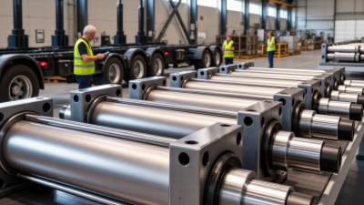
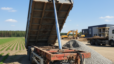
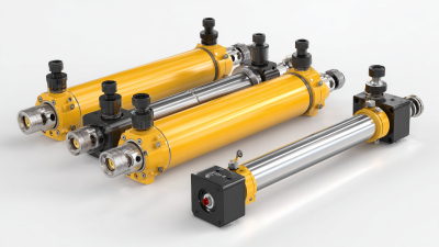
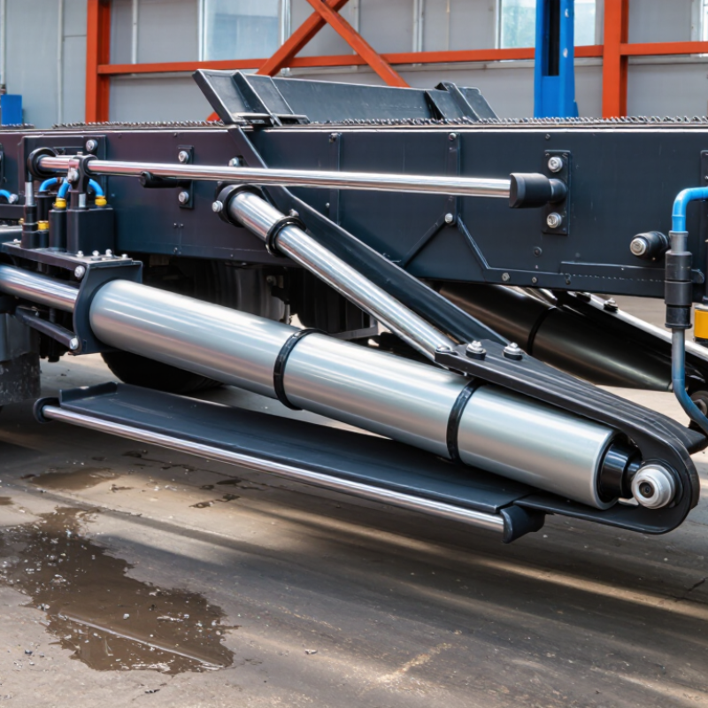
Underbody telescopic cylinders are hydraulic lifting devices installed beneath a dump body. Their nested steel stages provide long lifting strokes from a compact retracted length. Hydraulic fluid enters the cylinder base and creates pressure against the largest stage. That stage rises first, followed by smaller stages. The body then tilts for controlled material discharge. Some models use gravity for retraction, while others use hydraulic pressure. The design depends on the vehicle and lifting cycle.

Choosing the right cylinder starts with the actual load, not only the rated payload. Measure the required lifting angle, closed length, extended length, and available mounting space. Check hydraulic pressure, oil flow, pin size, and mounting alignment. A cylinder that fits on paper may still fail in service. Uneven loading can create side forces and accelerate seal wear. This detail is easy to overlook.

Field inspections often reveal damage around pins, welds, and exposed rod surfaces. Dirt, water, and road salt can enter worn seals. Regularly inspect leakage, unusual movement, bent stages, and loose mounting hardware. Keep the rod clean and lubricated according to the maintenance instructions. Corrosion protection matters in harsh environments. I have found that service access is sometimes ignored during selection. That mistake makes simple repairs unnecessarily difficult. A slightly larger cylinder is not always safer; pressure, stability, and chassis limits must remain balanced.

Which Vehicle and Tipping Requirements Should You Define First?

Before choosing an underbody telescopic cylinder, define the vehicle’s working conditions. Record the chassis type, wheelbase, body length, payload, and axle-load limits. A cylinder that fits an empty truck may interfere with the frame when the suspension compresses. Measure the available mounting space with the body lowered and raised.

Tipping requirements need equal attention. Specify the required tipping angle, lifting time, load distribution, and operating pressure. A short stroke may lift quickly but fail to reach the needed discharge angle. A longer stroke can create installation problems beneath a compact body. Check the pump’s flow rate, hydraulic pressure, pin positions, and cylinder retracted length together. Do not select these figures separately.

Consider the material being tipped. Wet soil, crushed stone, and scrap can create different starting forces. The load may also shift suddenly near the peak angle. That matters. In field inspections, I have found that uneven loading causes more trouble than the rated payload suggests. Recheck calculations against real loading habits, not ideal drawings. Temperature, dust, water exposure, and daily cycle frequency also influence seal and tube performance. A careful choice may still need adjustment after the first operating season. That is normal, but it should be monitored through leak checks, pin wear, and lifting-speed changes.

2026 How to Choose Underbody Telescopic Cylinders?

Define the vehicle class, payload range, body length, and required tipping angle before selecting cylinder stages, stroke, and lifting force.

The chart shows representative industry planning ranges for common tipper applications. Light-duty vehicles typically handle about 1.5–3 tonnes, medium-duty vehicles about 4–8 tonnes, and heavy-duty quarry or mining vehicles about 10–20 tonnes. Typical target tipping angles are approximately 45° for light and medium bodies and 50° for heavy-duty bodies. Final cylinder selection must also verify body length, hinge geometry, hydraulic pressure, center of gravity, and required safety margin.

How Do You Choose Cylinder Size, Stroke, and Lifting Capacity?

How to Choose Underbody Telescopic Cylinders in 2026

Choosing an underbody telescopic cylinder starts with the load, not the catalog. An industry market assessment published in 2024 forecasts hydraulic-cylinder demand rising from about $14.1 billion in 2024 to $18.2 billion by 2029. That growth reflects heavier equipment and tighter uptime expectations. Measure the body length, pivot position, loaded weight, and required tipping angle. Geometry decides.

Calculate cylinder force using F = pressure × piston area. At 250 bar, a 100 mm bore produces about 196 kN of theoretical force. Real output may fall near 167 kN after friction and hydraulic losses. Do not size from payload alone. Add body weight, uneven loading, cold-oil resistance, and a practical safety margin. A small bore may fit neatly, yet stall at the first lifting stage.

Stroke must follow the lifting path. Sketch the closed and raised positions, then check every stage of the telescopic sequence. Industry equipment reports commonly show dump bodies operating around 45 degrees, but actual requirements vary sharply by chassis and material. That figure is only a starting point. I have seen designs pass static calculations but struggle in winter service. That is not enough. Check rated pressure, oil flow, pin alignment, mounting strength, and retraction clearance against ISO 4413 principles. Allowing extra stroke can also create damaging end loads, so more is not always safer.

2026 How to Choose Underbody Telescopic Cylinders? – How Do You Choose Cylinder Size, Stroke, and Lifting Capacity?
Engineering reference: The figures below are general selection values for underbody telescopic cylinders. Actual lifting performance depends on cylinder angle, mounting position, tipping geometry, hydraulic pressure, oil flow, payload distribution, structural strength, and safety factors. Final selection should be verified using the complete vehicle lifting calculation.
1. Cylinder Size and Theoretical Thrust Reference
Minimum Effective Piston Diameter Recommended Hydraulic Pressure Theoretical Push Force at 200 bar Approximate Static Force Equivalent Reference Working Load at 80% Utilization Typical Application Guidance
80 mm 160–200 bar 100.5 kN 10.2 tonnes-force 8.2 tonnes Light-duty bodies, compact trailers, and applications with moderate tipping resistance.
90 mm 160–200 bar 127.2 kN 13.0 tonnes-force 10.4 tonnes Medium-duty tipping bodies where installation space and payload are balanced.
100 mm 180–220 bar 157.1 kN 16.0 tonnes-force 12.8 tonnes General-purpose medium and heavy-duty dump body applications.
110 mm 180–220 bar 190.1 kN 19.4 tonnes-force 15.5 tonnes Heavy-duty bodies requiring higher starting force or greater resistance to load shift.
120 mm 180–250 bar 226.2 kN 23.1 tonnes-force 18.5 tonnes Large heavy-duty bodies, high center-of-gravity loads, and demanding operating cycles.
Theoretical push force: F = p × A
Where: F = cylinder force, p = hydraulic pressure, and A = piston area.
At 200 bar: F(kN) ≈ 0.015708 × D², where D is the piston diameter in millimetres.
2. Stroke and Installation Dimension Selection
Nominal Stroke Typical Retracted Length Typical Extended Length Recommended Body Length Range Typical Lifting Angle Range Selection Notes
600 mm 500–650 mm 1,100–1,250 mm 3.5–5.0 m 35–45° Suitable where chassis space is limited and a short tipping body is used.
900 mm 650–800 mm 1,550–1,700 mm 4.5–6.0 m 38–45° A common compromise between installation length, body size, and lifting height.
1,200 mm 800–950 mm 2,000–2,150 mm 5.5–7.0 m 40–48° Appropriate for longer dump bodies and applications requiring greater discharge height.
1,500 mm 950–1,100 mm 2,450–2,600 mm 6.5–8.0 m 42–50° Used for long bodies, high sideboards, and material that needs a steeper discharge angle.
1,800 mm 1,100–1,300 mm 2,900–3,100 mm 7.5–9.0 m 45–52° For extra-long bodies; confirm chassis clearance, stability, and maximum permissible height.
Stroke rule: Select the shortest stroke that achieves the required unloading angle. Excessive stroke increases extended length, bending risk, vehicle instability, and hydraulic oil demand.
3. Practical Selection Matrix by Vehicle and Body Load
Approximate Payload Range Typical Body Length Suggested Minimum Effective Diameter Suggested Stroke Recommended System Pressure Design Priority
Up to 5 tonnes 3.5–5.0 m 80–90 mm 600–900 mm 160–200 bar Compact installation, low tare weight, and adequate starting force.
5–10 tonnes 4.5–6.0 m 90–100 mm 900–1,200 mm 180–220 bar Balanced force, stroke, oil volume, and operating cycle life.
10–15 tonnes 5.5–7.0 m 100–110 mm 1,200–1,500 mm 180–220 bar High starting force and sufficient stability during the first lifting stage.
15–20 tonnes 6.5–8.0 m 110–120 mm 1,500–1,800 mm 200–250 bar Structural strength, pressure control, side-load resistance, and thermal management.
Over 20 tonnes 7.5 m and above 120 mm or larger, or multiple cylinders Based on geometry Validated by complete system calculation Use a detailed tipping analysis rather than selecting by payload alone.
4. Key Technical Parameters to Confirm Before Ordering
Parameter Recommended Verification Method Why It Matters Typical Acceptance Consideration
Maximum working pressure Compare cylinder rating with the hydraulic relief-valve setting. Prevents overload, seal damage, tube deformation, and premature fatigue. Cylinder working pressure should exceed the actual system relief setting.
Starting force Calculate the highest resistance at the beginning of the lifting cycle. The first lifting stage usually requires the greatest force because the body angle is low. Include friction, material adhesion, uneven loading, and cold-weather effects.
Stroke reserve Compare required body angle with full cylinder extension. Prevents bottoming-out and ensures the body reaches the required discharge angle. Allow a practical reserve without creating excessive extension.
Retracted length Measure chassis, subframe, propeller shaft, axle, and body-clearance zones. Insufficient clearance can cause interference or damage during road operation. Check the complete suspension and articulation range.
Side-load resistance Review mounting alignment and expected lateral movement. Telescopic cylinders are primarily designed for axial load; side loads accelerate wear. Use suitable guides, trunnions, spherical mounts, or mechanical alignment devices.
Oil volume and pump flow Calculate cylinder volume and compare it with pump output. Determines lifting speed, reservoir size, heat generation, and cycle time. Ensure the reservoir can supply the cylinder without aeration or cavitation.
Mounting and load distribution Check pin diameter, bracket thickness, weld design, and load path. The cylinder may be strong enough while the mounting structure is not. Verify the complete chassis and subframe assembly, not only the cylinder.
Operating environment Identify temperature, dust, water, salt, impact, and cleaning conditions. Environmental exposure affects seals, coatings, oil viscosity, and service life. Select sealing and surface protection suitable for the operating environment.
5. Recommended Selection Sequence
Step Action Output
1 Record gross vehicle weight, payload, body weight, body length, and load distribution. Basic operating load case.
2 Determine the required maximum tipping angle and available installation space. Required stroke and dimensional envelope.
3 Calculate the highest cylinder force required at the start of lifting. Minimum effective piston diameter.
4 Apply a suitable safety margin for friction, uneven loading, and dynamic effects. Design force and pressure requirement.
5 Check mounting alignment, pin loads, side clearance, and chassis strength. Mechanically compatible installation.
6 Verify pump flow, oil volume, relief pressure, hoses, and reservoir capacity. Compatible hydraulic system.
7 Validate the complete system through a lifting-cycle and stability review. Final cylinder specification and safe operating range.
Important: Cylinder thrust is not equal to payload capacity. The actual payload that can be lifted depends on the moment relationship between the cylinder mounting points, body hinge location, body center of gravity, friction, and the minimum tipping angle.

Which Materials, Mounting Options, and Safety Features Matter?

2026 How to Choose Underbody Telescopic Cylinders?

Material selection affects service life beneath a truck or trailer. Choose a honed steel barrel for consistent pressure control and smooth internal movement. A chrome-plated piston rod resists scoring, moisture, and road debris. However, chrome quality and thickness vary between suppliers. Ask for coating specifications, seal compatibility, and corrosion test data. Polyurethane or reinforced seals can handle pressure changes, but they still need suitable hydraulic oil and temperature ratings.

Mounting design matters as much as cylinder strength. A center-mounted cylinder can distribute lifting force effectively when the frame is rigid. Trunnion or pivot mounts allow movement during tipping and reduce side loading. Pin alignment should be checked with the body fully lowered. Even a small offset can create uneven wear. I once saw a cylinder fail early because the mounting bracket looked strong but forced the rod sideways. That shortcut was expensive.

Safety features deserve direct attention. A velocity fuse can limit sudden descent after hose damage. A pressure relief valve helps prevent overload during uneven loading. Mechanical body supports are essential during maintenance; hydraulic pressure alone is not a safe support. Add guards around exposed rods where gravel can strike them. Check rated pressure, stroke length, retracted clearance, and working temperature before installation. Field inspections should include leaks, bent pins, cracked welds, and unusual noise. Documentation helps, although real operating conditions often reveal weaknesses that specifications miss.

How Should You Compare Suppliers, Maintenance Needs, and Total Cost?

Choosing underbody telescopic cylinders starts with the supplier, not the lowest quotation. Ask for load charts, extension-cycle data, material certificates, and test records. A reliable supplier explains how bore size, stroke length, mounting angle, and hydraulic pressure affect stability. Request samples from the same production process used for regular orders. Factory visits help, but documents still matter. Check response times for seal kits and technical questions. If every answer is vague, pause.

Maintenance needs should be visible before installation. Compare chrome thickness, wiper design, port protection, and seal availability. A cylinder beneath a truck faces water, grit, road salt, and sudden temperature changes. Specify inspection intervals for leaks, rod scoring, loose mounts, and uneven extension.

Ask whether seals can be replaced without removing the entire assembly. That detail can save hours.

In practice, operators sometimes ignore early oil film because the lift still moves. That is a costly habit. I have seen a small nick become a damaged rod after repeated dusty cycles.

Total cost includes purchase price, freight, oil loss, downtime, labor, and disposal of worn parts. Compare service life under your real duty cycle, not only a laboratory rating. A cheaper cylinder may need two seal changes each year. A higher-priced unit may reduce idle time, but only if parts arrive quickly.

Build a five-year worksheet using cycle count, load, climate, and repair hours. Leave room for uncertainty. Field conditions rarely match the spreadsheet. Also verify warranty exclusions, training support, and the supplier’s response when failures repeat.